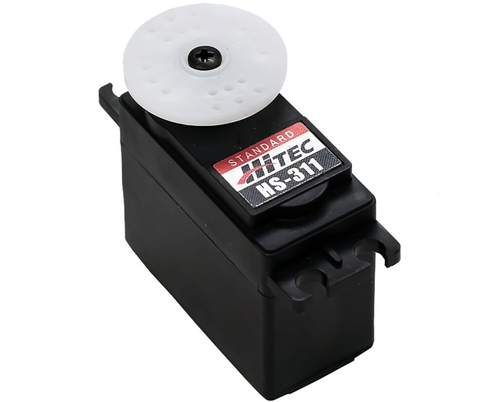
As Servos we are using the Hitec HC-311 servos which are standard servos from RC hobby.
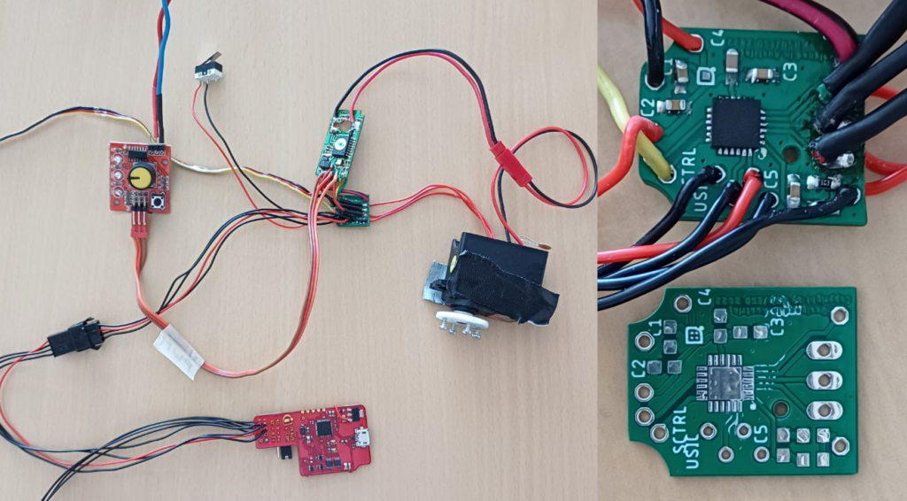
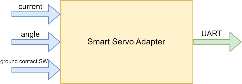
These servos get a PWM signal containing the target angle. The servo tries to reach this target angle as fast es possible. If the servo do not have enough force to get into the position or max it out there is no feedback back to the AI. For AI training it is essential to get as much feedback as possibly. Therefore we need additional electronic components to measure these. Our previous team already designed a PCB that get integrated into the servos. These is measuring the servo internal potentiometer to get the actual angle value. Via a shunt resistor the current of the servo is measured. The ground contact switch of each leg get also digitalized by this board.
All the information get transmitted to the FPGA board via UART. The FPGA forwards the info to the linux where the data get used as feedback information for the AI.
Current issues
The previous team also integrated a current sensor to measure the servo current, but this concept has some disadvantages in the current PCB implementation:
In general, we have larger interference on the 5V supply line to due of the consumption of the servos. All servo uses a PMW signal to drive the motor. (Hitec HS-311 max~500mA) This leads to a very noisy supply. A Single Servo generates with the current setup ~Vpp 200mV noise.
On the 3,3V line we get a relative clean signal with ~Vpp 20mV. But the motor generates high frequency noise up to ~Vpp 1,2V. Improvement: A 100nF kerko soldered directly to the motor connections. And solder the minus to the housing leads in a bit less noise of ~Vpp 600-800mV
Therefore a current measurement with a shunt (100mR => max 50mV) directly connected to the mircrocontroller leads to inaccurate measurement. Also the shunt rise the ground of the servo PCB and therefore also the voltage of the poti. This leads in additional inaccuracies in measurement of the is angle of the servo. As quick fix we implemented a IIR filter. To due that we sample with a much higher frequency than we need the data, we get a relative good signal.
Software
The smart servo adapter holds an XMC1100 Infinion microcontroller. The microcontroller code is written in C and programmed by a Segger J-Link via SWD. As IDE we used the eclipse based IDE Dave from Infinion which is similar to the STM32 Cube IDE for STM32 microcontroller.
UART Protocol
As physical layer for sending the information from the servo to the FPGA a UART used.
Synchronisation
For synchronisation and recognise of the first byte of the message a break time between two messages is defined.
Breakout Board
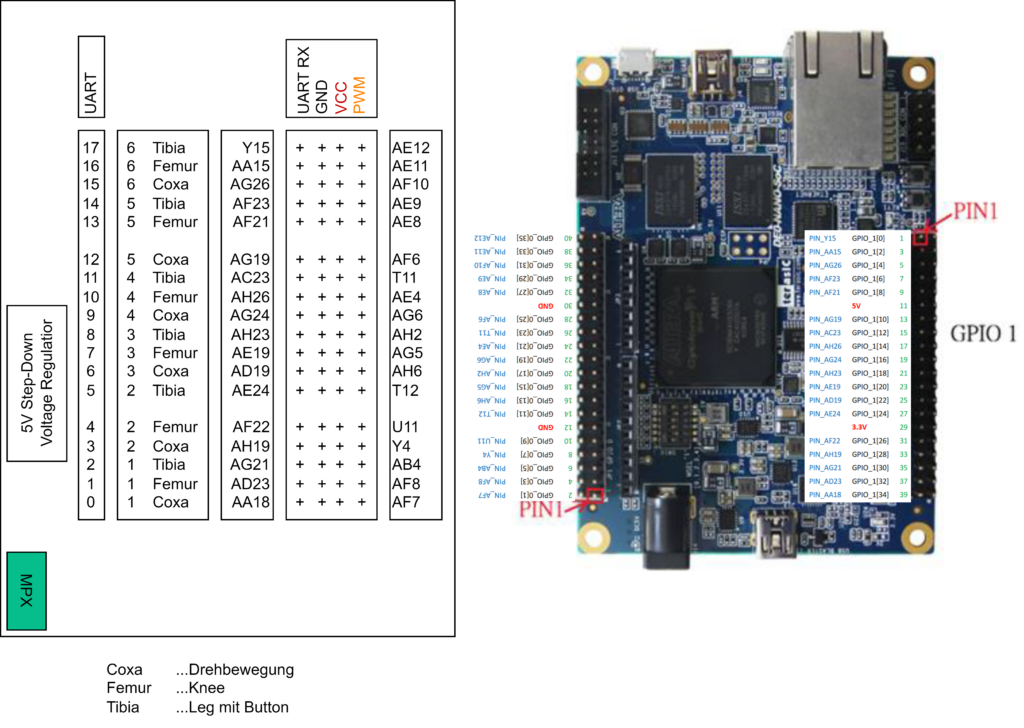
The DE0-Nano-SoC board provides a lot of GPIO pins. These pins are used to connect all peripherals, like servos, lidar sensor or gyro. The breakout board contains the 5V voltage regulator for the DE0-Nano-SoC board and fan out the pins from the pcb connector to the servo connectors, ultrasonic sensor and gyro. The breakout board was reused from the previous teams and adapted to the new servos and changed requirements.
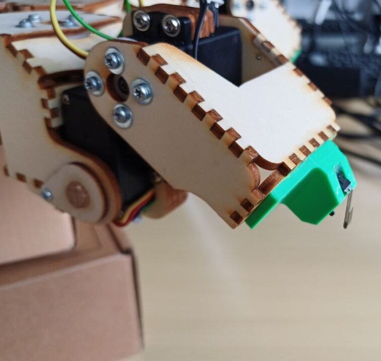
Ground Contact Switches
To detect if the arms stands on the floor a switch is added to the legs.
The former team also developed a 3D-printed switch. But these was not working reliable. These new switches are much better.